Graphical Description of the Structure of the plastic Injection Mold
Graphical Description of the Structure of the Plastic Injection Mold
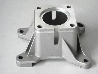
Plastic Injection Molding is a processing method used in mass production of some complex-shaped parts. The specific principle refers to: the plastic raw materials melted by heat are pushed by the screw of the injection molding machine into the cavity of the plastic mold under high pressure, and after cooling and solidification, the plastic molded product is obtained.
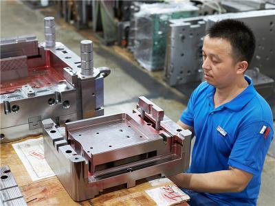
The plastic mold is composed of a movable mold and a fixed mold. The movable mold is installed on the movable template of the injection molding machine, and the fixed mold is installed on the fixed template of the injection molding machine. During injection molding, the movable mold and the fixed mold are closed to form a pouring system and a cavity. When the mold is opened, the movable mold and the fixed mold are separated to take out the plastic products.
Although the structure of the plastic mold may vary widely due to the variety and performance of the plastic, the shape and structure of the plastic product, and the type of the injection machine, the basic structure is the same.
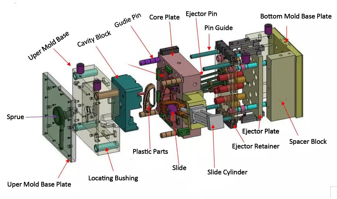
I. The structure of the plastic injection mold is divided by function, which is mainly composed of: pouring system, temperature control system, molding parts system, exhaust system, guide system, ejection system, etc. Among them, the pouring system and the molded parts are the parts that are in direct contact with the plastic and change with the plastic and the product. They are the most complex and the most variable parts in the plastic mold, requiring the highest processing finish and precision.
1. Gating system: refers to the runner part before the plastic enters the cavity from the nozzle, including the main runner, cold slug, runner and gate, etc.
2. Forming parts system: refers to the combination of various parts that constitute the shape of the product, including movable mold, fixed mold, cavity (concave mold), core (punch mold), molding rod, etc. The core forms the inner surface of the product, and the cavity (concave mold) forms the outer surface shape of the product. After the mold is closed, the core and the cavity constitute the cavity of the mold. According to process and manufacturing requirements, sometimes the core and die are combined by several pieces, sometimes as a whole, and inserts are only used in the parts that are easy to damage and difficult to process.
3. Temperature adjustment system: In order to meet the mold temperature requirements of the injection process, a temperature adjustment system is required to adjust the temperature of the mold. For injection molds for thermoplastics, the cooling system is mainly designed to cool the mold (the mold can also be heated). The common method of mold cooling is to open a cooling water channel in the mold, and use the circulating cooling water to take away the heat of the mold; the heating of the mold can not only use the cooling water to pass hot water or hot oil, but also install inside and around the mold. Electric heating element.
4. Exhaust system: It is set up to remove the air in the cavity and the gas generated by the melting of the plastic during the injection molding process to the outside of the mold. When the exhaust is not smooth, the surface of the product will form air marks (air lines), scorching, etc. Poor: The exhaust system of a plastic mold is usually a slot-shaped air outlet opened in the mold to discharge the air in the original cavity and the gas brought in by the melt. When the melt is injected into the cavity, the air originally stored in the cavity and the gas brought in by the melt must be discharged out of the mold through the exhaust port at the end of the material flow, otherwise the product will have pores, poor connection, Dissatisfaction with the filling of the mold, and even the accumulated air, which burns the product due to the high temperature generated by the compression. Under normal circumstances, the vent can be located either at the end of the melt flow in the cavity or on the parting surface of the mold. The latter is a shallow groove with a depth of 0.03-0. 2mm and a width of 1.5-6mm on one side of the cavity. During injection, there will not be a lot of molten material in the vent hole, because the molten material will cool and solidify at the place and block the channel. The opening position of the exhaust port should not be facing the operator to prevent accidental spraying of molten material and hurting people. In addition, the matching gap between the ejector rod and the ejector hole, the matching gap between the ejector block and the stripper plate and the core can also be used for exhaust.
5. Guiding system: It is set up to ensure that the movable mold and the fixed mold can be accurately centered when the mold is closed, and a guiding component must be set in the mold. In the injection mold, four sets of guide posts and guide sleeves are usually used to form the guide parts. Sometimes, it is necessary to set mutually coincident inner and outer cones on the movable mold and the fixed mold to assist positioning.
6. Ejection system: generally includes: thimble, front and rear thimble plates, thimble guide rod, thimble return spring, thimble plate locking screw and other components. When the product is formed and cooled in the mold, the front and rear molds of the mold are separated and opened, and the ejection mechanism-the ejector pin pushes the plastic product and the condensate in the runner out or pulls out of the mold cavity and runner position under the push of the ejector pin of the injection molding machine. , In order to proceed to the next injection molding work cycle.
II. Plastic molds are generally composed of mold bases, mold cores, auxiliary parts, auxiliary systems, auxiliary settings, and dead-angle treatment mechanisms according to their structure.
1. Mold base: Generally, we don’t need to design it. You can order it directly from the standard mold base manufacturer, which greatly saves the time required to design the mold, so it is called the plastic mold standard mold base. It constitutes the most basic frame part of the plastic mold.
2. Mold core: The core part is the core part of the plastic mold, and it is the most important part of the mold. The forming part of the plastic product is inside the mold core, and most of the processing time is also spent on the mold core. However, compared to some relatively simple molds, it has no core part, and the product is formed directly on the template. Most of the early plastic molds were like this, and they were relatively backward.
3. Auxiliary parts: Commonly used auxiliary parts for plastic molds include positioning ring, sprue bushing, thimble, grab pin, support column, ejector plate guide post and guide bushing, garbage nails, etc. Some of them are standard parts. Order directly when ordering the mold base, and some parts need to be designed by yourself.
4. Auxiliary system: There are four auxiliary systems for plastic molds: pouring system, ejection system, cooling system and exhaust system. Sometimes, because the plastic materials used need to be heated at a high temperature, some molds will also have a heating system.
5. Auxiliary setting: The auxiliary setting of the plastic mold is equipped with eye hole, KO hole (top stick hole) and so on.
6. Dead angle treatment structure: When the plastic product has dead angles, the mold will have one or more dead angle treatment structures. Such as sliders, inclined roofs, hydraulic cylinders, etc. In most domestic books, this mechanism for dealing with dead ends is referred to as the “removal mechanism”.
In fact, plastic molds are not difficult. No matter how the plastic product changes, the structure of the mold used to form the plastic product is nothing more than the above-mentioned aspects. The difference between molds is whether the mold is large or small? The locations or methods of the various auxiliary parts, auxiliary settings, and auxiliary systems are different. The method, structure, size, etc. of dealing with dead ends have changed. Of course, the design experience is particularly important if the designed mold is simple to process, easy to assemble, long in life, moderate in price, and good in formed products. Good experience can deal with problems in design and processing, and it is also relatively safe to deal with design changes.
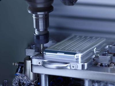
III. The structure and composition of the injection machine: A general-purpose injection machine mainly includes an injection device, a mold clamping device, a hydraulic drive system and an electrical control system. The main function of the injection device is to plasticize the plastic uniformly, and to inject a certain amount of melt into the cavity of the mold with sufficient pressure and speed. The injection device is mainly composed of plasticized parts (composed of screw, barrel and nozzle), as well as hopper, transmission device, metering device, injection and mobile cylinder, etc.
Clamping device: Its function is to realize the opening and closing of the mold, and to ensure that the molding mold is reliably closed and the product is ejected during injection. The mold clamping device is mainly composed of front and rear fixed templates, movable templates, tie rods for connecting front and rear templates, and mold clamping cylinders. , Link mechanism, mold adjustment device and product ejection device.
Hydraulic system and electrical control system: its function is to ensure that the injection machine works accurately and effectively according to the predetermined requirements (pressure, speed, temperature, time) and action sequence of the process. The hydraulic system of the injection machine is mainly composed of various hydraulic components and circuits and other auxiliary equipment. The electrical control system is mainly composed of various electrical appliances and instruments. The hydraulic system and the electrical system are organically organized to provide power and realization for the injection machine control.
 Building A, Dingfeng High-tech Park, Shapuwei Community, Song Gang Street, Shenzhen, China, 518105
NO.1 Jinchang Road, Henan Industrial Zone, Chang’an Town, Dongguan City, China


For inquiries about our products or pricelist, please leave to us and we will be in touch within 24 hours.
© Copyright: 2026 Lyter Engineering Ltd. All Rights Reserved

IPv6 network supported
 English