Home

Services

Design & Engineering


Injection Mould Design & Engineering


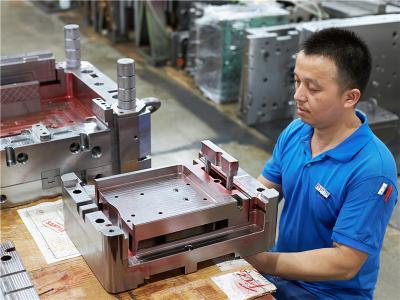
Lyter’s tooling design and engineering team has over 16 years experiences in mold making industry.


The team member includes experienced product and plastic injection mould design engineers, as well as mould making technicians with excellent craftsmanship.


With years of tooling design and manufacturing and cooperation with reputational companies, such as GE, Whirlpool, Honda etc. from automotive and appliances industry, the company now has developed an effective management system to bring our values and expertise to meet customers satisfaction.


Our engineering department has 28 employees, include 22 engineers and 6 technicians, half of them has a good understanding of technical English, can read, write, listen and speak to customers fluently without language barrier. Our team has capacity to support your product design & development from very early stage to the production end.


Automotive Plastic Injection Mould Design


Mould DFM Analysis Report


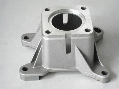
Injection Mold DFM Report Submission and Approval


For every plastic injection mould project, Lyter will provide a detailed DFM report to carry out the research on part visible area specifications, parting line on major and important mold inserts, the mold layout and basic sizes, the mold ejection layouts, gate details, draft the thickness analysis, cooling channel proposal for cavity inserts and critical areas, improvement proposals and product engraving specifications etc. We start to design the plastic injection mould after DFM approval by customer.


The DFM (Design For Manufacture) Analysis Report allows both customer and us to identify and fix any issues that might happen in the tools manufacturing phase to save timing and costs.


Normally it takes 1-2 working days to finish the DFM for a normal injection moulds DFM. If there is special urgency need, customer can feel free to discuss with us and we will move quicker to support.


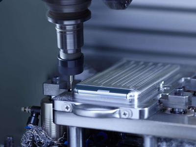
Moldflow Rheological Analysis


Our Moldflow Analysis includes


  • Plastic Material Analysis
  • Wall Thickness Analysis
  • Feed System Analysis
  • Processing Conditions
  • Filling Process
  • Filling Time
  • The Pressure at V/P Switchover
  • The Temperature at the Flow Front
  • Sink Marks Estimate
  • Average Volumetric Shrinkage
  • Weld Lines
  • Defection—X, Y, Z—direction
  • Air Traps
  • Injection Pressure & Clamp Force


MoldFlow report will be provided when it is required or necessary. By iterating the simulation of molding, we can optimize product design and the mold design, to get rid of unnecessary modifications to both part and the mold, saving costs and timing for the project.

Mold Flow Analysis For Plastic Injection Mould


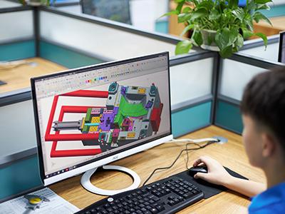
Mould 3D Design and Approval


We will get started on the mould 3D design after the DFM report is approved by customer.


With 3D design by Unigraphics (NX11), we will combine all design key points for the specific part and notes or clarifications that were communicated and mutually agreed on DFM report together.


The detailed and vivid mould 3D model also help our customer to examine if all specific needs are met in the design. Normally it takes 5-7 working days to finish the 2D and 3D tooling design if the part structure is not that complicated.


2D and 3D Tooling Design


Case study
Plastic Tooling Engineering
Application Market

  • metal list
    APPLIANCE
  • 123
    ENERGY
  • More than 35 years of combined injection-moulding know-how
    AUTOMOTIVE
  • Customised design and development
    MEDICAL
  • Our own tool- and mould manufacturing
    ELECTRONICS
  • Professional service from a single source
    INDUSTRIAL
  • Short delivery times due to manufacturing in Germany
    AVATION
  • Certification according to DIN EN 9100, 9001 and 14001
    CONSUMER
  • What should we pay attention to for Hot Runner Mold Design?

  • What Are the Key Points for Mould Design?

  • Mold & Part Design Keypoints-Automobile Lamp Products-a

  • Mold & Part Design Keypoints-Automobile Lamp Products-b

  • Mold & Part Design Keypoints-Automobile Lamp Products-c

  • Mold & Part Design Keypoints-Automobile Lamp Products-d

  • Mold & Part Design Keypoints-Automobile Lamp Products-e

  • Mold & Part Design Keypoints-Automobile Lamp Products-f

  • Mold & Part Design Keypoints-Automobile Lamp Products-g

  • Mold & Part Design Keypoints-Automobile Lamp Products-h

1.To determine the gate location according to the plastic part structure and usage requirements. As long as the structure allows, the nozzle and nozzle head in the fixed mold insert does not interfere with the molding structure, and the gate of the hot runner system can be at any position of the plastic part. The position of the injection gate for conventional plastic injection molding is usually selected based on experience. For large and complex special-shaped plastic parts, the position of the injection molding feed inlet can be simulated by computer-aided analysis (CAE) to simulate the flow of molten plastic in the cavity, analyze the cooling effect of each part of the mold, and determine the ideal gate location.
2.Determining the nozzle head form of the hot runner system. Product material and use characteristics are the key factors for choosing the nozzle head form, and the production batch of plastic parts and the manufacturing cost of the mold are also important factors for choosing the nozzle head form.
3.The number of cavities per mold is determined by the production batch of the product and the tonnage of the injection machine.
4.The number of nozzles is determined by the position of the glue inlet and the number of cavities per mold. If you form a product, choose one mold and one feed inlet, you only need one nozzle, that is, use a single-head hot runner system; if you form a product, choose one mold with multiple cavities or one mold with one cavity with more than two feeds If you want to open the nozzle, you need multiple nozzles, that is, a multi-head hot runner system is used, except for the mold structure with a cross runner.
5.To decide the radial size of the nozzle accords to the weight of the plastic part and the number of nozzles. At present, the nozzles of the same form have multiple size series, which meet the requirements of forming plastic parts in different weight ranges.
6.Deciding the mold structure size according to the plastic part structure, then select the nozzle standard-length series size according to the thickness of the fixed mold insert and the fixed template, and finally trim the thickness of the fixed template and other dimensions related to the hot runner system.
7.Confirming the shape of the hot runner fixing plate according to the shape of the hot runner plate, arrange the power cord lead groove on the plate, and design an adequate cooling water loop near the hot runner plate, nozzles, and nozzle heads.
1. The overall layout of the mold is reasonable
2. Parting surface selection
3. Layout of 3 runners, selection of glue inlet
4. ejection device
5. water transport arrangement
6. exhaust options
7. Pay attention to the draft angle when parting the mold, the extraction of inserts, the treatment of the rubbing angle, and the selection of material shrinkage
8. Processing drawings should be detailed, but simple.
All in all, mold design must consider the ability to demould! Easy to process and to eject!


© Copyright: 2024 Lyter Engineering Ltd. All Rights Reserved

IPv6 network supported

top