Design of injection mold for head of cleaner
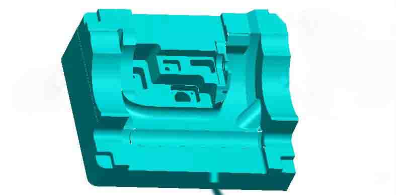
The head of cleaner's function is similar to a mop, and it is an advanced cleaning tool driven by electricity. The maximum external dimension of the product is 335.00 mm x 250.50 mm x 133.67 mm, the average thickness of the plastic part is 2.56 mm, the material is ABS, the shrinkage rate is 1.006, and it’s 334.04 grams. The technical requirements for the plastic parts are that there must be no defects, such as flash, short shot, flow lines, gas mark, warpage deformation, silver streaks, unevenness etc.
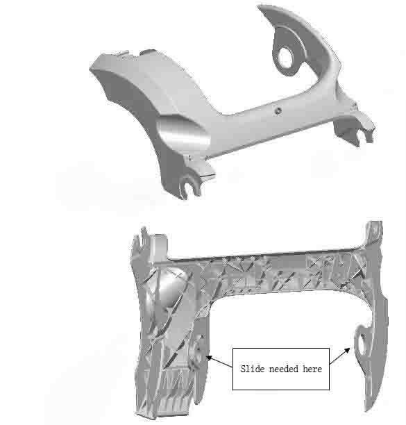
We can see from the picture above, the plastic part structure is shaped as a complex irregular shell. There is one place on the inner and outer sides that needs to be designed for slider core pulling. There are many deep ribs on the back of the plastic part, and inserts need to be designed to solve the problems of mold manufacturing and injection venting. The ribs inside the plastic part is designed with undercuts in many places, and it is necessary to design a lifter to demould. See the 3D drawing of the cleaning head mold. The size of the plastic parts is large, the mold is a large mold, and needs 400-ton injection molding machine. This mold is 1 cavity, and the mold base is CI6080, A180 B270 C190; the specifications of the mold base exceed those of the standard mold base. Correspondingly, the size of mold cavity and core is larger, the size of the cavity is 470*360, and the weight reaches more than 150kg. The four corners of the cavity and core are designed with interlock, and the M20 lifting process holes are drilled and tapped to facilitate the handling of mold parts. According to the theory of ergonomics, generally parts over 20kg must be lifted by a crane. The lower frame method of the cavity and core is the reference angle positioning, and the two sides away from the reference angle are all designed with squeeze blocks to be fixed. This is the basic form of large mold core framing.
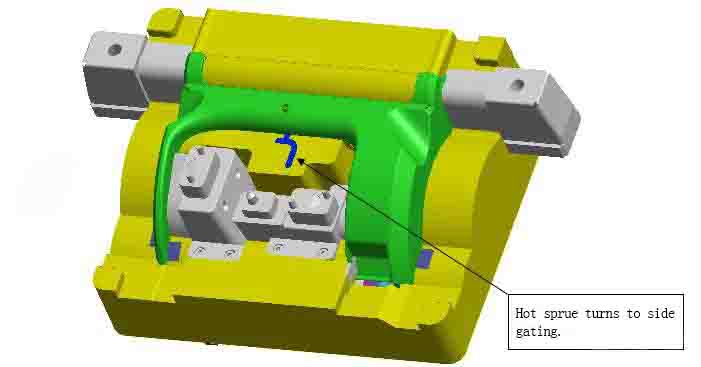
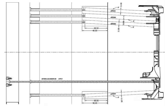
The top surface of the plastic parts is all the appearance surface, and the gate cannot be designed. The size of the parts is large, the ribs is complicated, and the process of plastic melting is long. Therefore, it is very important to design the gating system reasonably. The gate position is designed at the higher part of the center of the plastic part. Due to the steep parting surface and the slider core pulling in the middle, the gate can only be a point gate or a single hot nozzle. After the melting resin reaches the parting surface, it is transferred to the sub gate to eject.
The 4 sliders of the core are all driven by inclined guide pins, and wear plates are designed on the slope and bottom of the slider to facilitate the adjustment and replacement of the mold fitting. Due to the limited space of the two sliders in the middle, a wedge is used to drive the two sliders. When designing a mold with two sliders driven by one wedge, be careful to make the slider slope and core pulling distance on both sides as equal as possible.
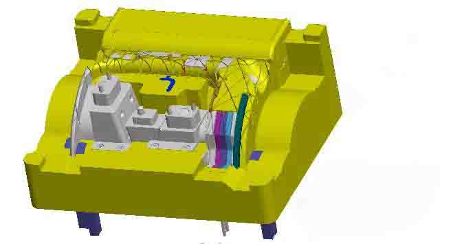
The core has multiple ribs, and the venting of the mold is very important. Multiple inserts are designed to be spliced together to facilitate venting. At the same time, it is beneficial to electrode and polishing. Please kindly see the below picture. There is big height difference between the plastic parts, so the movable mold plate is thick, and the depth of the core frame is large. At this time, the way to fix the inserts should be paid attention. There are many ways. Large inserts must be secured from the bottom with screws. Small inserts, but those with rubber rings at the bottom should be fixed with screws. Especially small inserts should not be fixed with screws as much as possible. Because the length of the small screws is limited, the holes are very deep on the larger mold plate, and the installation of small screws is limited by vision, so it is not easy to see clearly, and it is especially prone to missing screws.
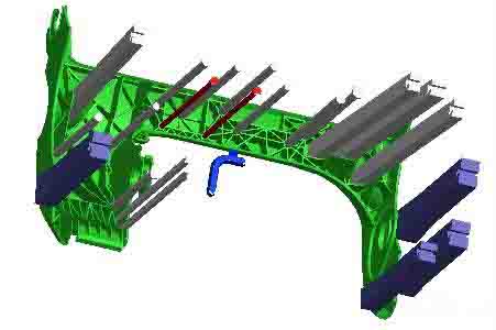
There are more ribs in the core of the plastic part, and the tightening force on the movable mold is large. Next to the rib, multiple ejector pins are designed to be ejected. Due to the large thickness of the B plate, the mold lifter is very long, and the lifter cannot be widened due to the close distance between the ribs and the limitation of the space. Therefore, in order to avoid the lack of rigidity caused by the long lifting, the design method of the two-lifter is adopted.
 Building A, Dingfeng High-tech Park, Shapuwei Community, Song Gang Street, Shenzhen, China, 518105
NO.1 Jinchang Road, Henan Industrial Zone, Chang’an Town, Dongguan City, China


For inquiries about our products or pricelist, please leave to us and we will be in touch within 24 hours.
© Copyright: 2026 Lyter Engineering Ltd. All Rights Reserved

IPv6 network supported
 English