Experience Sharing On Plastic Injection Tool Submarine Gate Design
Experience Sharing On Plastic Injection Tool Submarine Gate Design
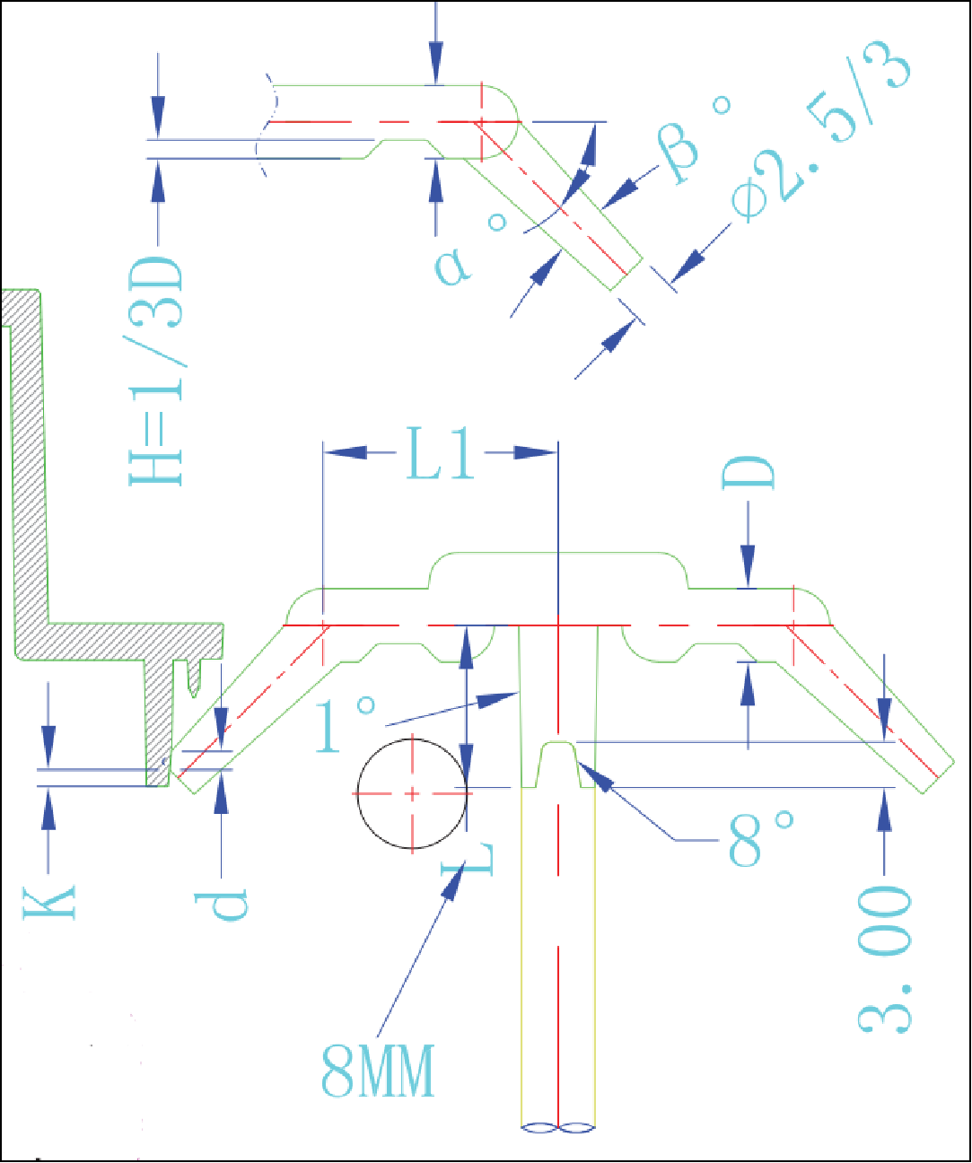
1) The included angle of α° can be designed in the range of 60° to 35°, depending on the height of the position that submarine gate is located.
2) The included angle of β° can be designed in the range of 8° to 20°, the bigger the better for the gate demolding.
3) L1>8 and L1.>2*D, so that the submarine gate can be easier to demould;
4) K>1mm, mainly to prevent the nozzle from dragging up the residue when it is broken, affecting the size and affecting the part’s assembly.
Three forms and usage scenarios of submerged gate breakpoints:
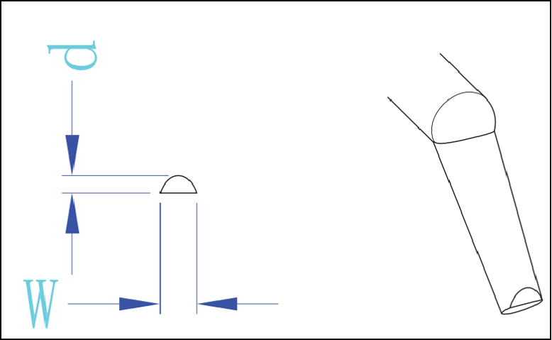
1) Oval shape: The nozzle cools quickly and the molding cycle is short, which is suitable for products with small plastic parts and appearance parts.
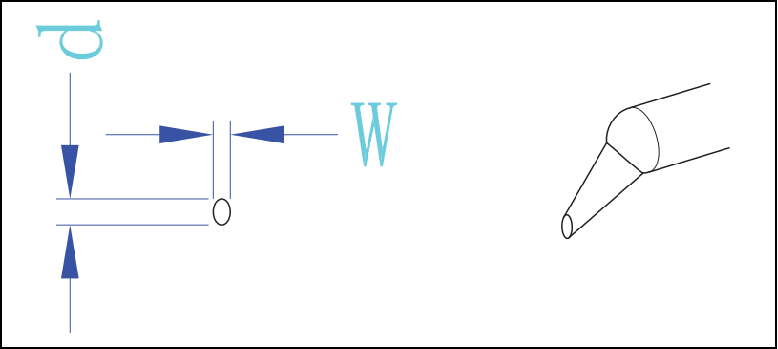
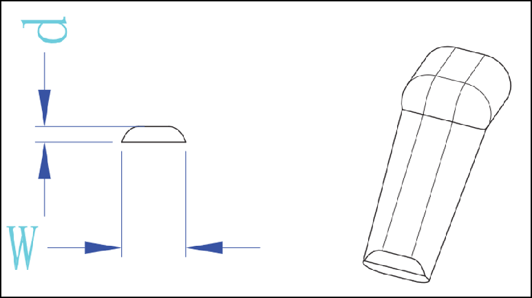
2) D shape: The head of the gate is large, which has a thermal insulation effect, which can delay the cooling of the gate and facilitate sufficient part packing during molding process, which is suitable for most plastic products.
3) Duckbill shape: When the ordinary D-shaped gate cannot meet the demand of material injection, the position of the submarine gate can be widened laterally, and the shape is similar to that of a duckbill.
Details of submarine gate design and product defect prevention for products with high appearance requirements
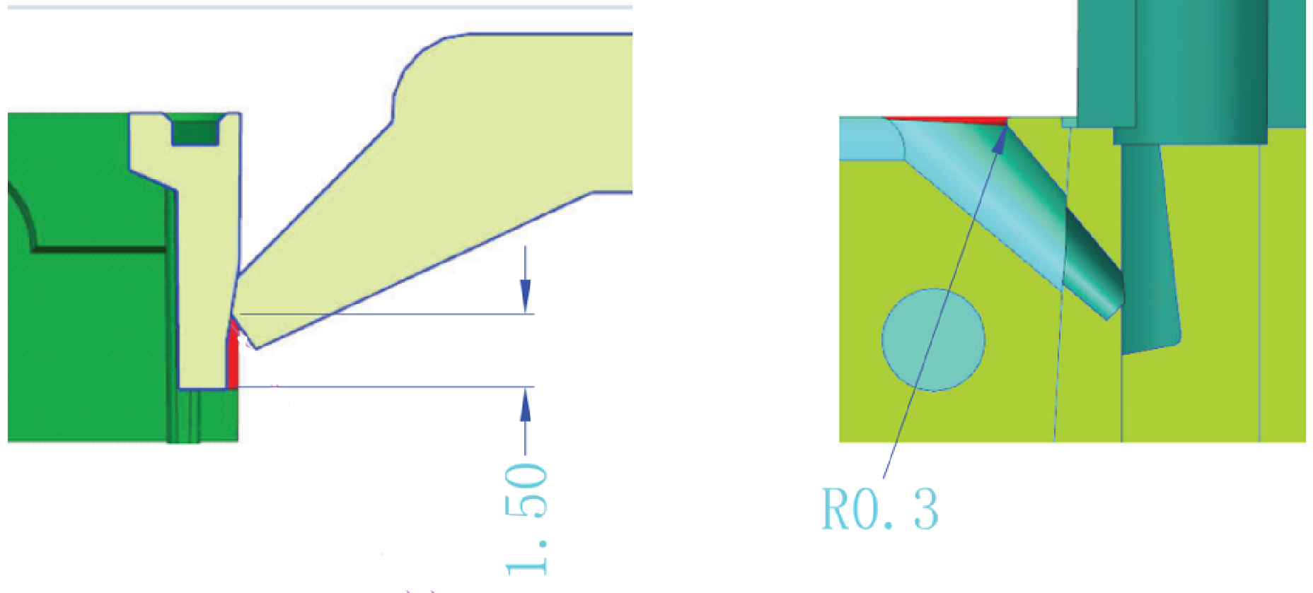
1) The position of the gate corresponds to the product, as shown in the schematic diagram, to reduce the part material. The purpose of this design is that even if there is a slight residue at the gate position, it will not cause the hanging plastic to remain in the cavity, causing the next cycle, the residual material rushes to the surface of the product to affect the appearance.
2) To round the edge by R0.3 at the position shown in the figure at the submarine gate to prevent the gate from hitting the sharp corner when demoulding and leaving the material powder in the mold cavity, causing the residual material to be flushed to the surface of the product when the next cycle and affecting the appearance.
Categories
latest blog
 Building A, Dingfeng High-tech Park, Shapuwei Community, Song Gang Street, Shenzhen, China, 518105
NO.1 Jinchang Road, Henan Industrial Zone, Chang’an Town, Dongguan City, China


For inquiries about our products or pricelist, please leave to us and we will be in touch within 24 hours.
© Copyright: 2026 Lyter Engineering Ltd. All Rights Reserved

IPv6 network supported
 English