In view of the shrinkage and deformation of the gear and the unrequired precision of the gear shaft hole during the injection molding of the plastic gear, the optimized design of the gating system, the demolding mechanism and the cooling method are used to produce the precision plastic gear that meets the requirements, thereby improving the gear’s performance. performance.
1. With the rapid development of industry, people have a great demand for cameras, printers and copiers in daily life and office. Plastic gears have gradually replaced metal gears. These equipments have relatively high requirements for gear meshing accuracy. In the design of the parting surface of the gear plastic part, the tooth-shaped inserts with the same shape of the fixed mold cavity and the movable mold core design adopt a layout of 1 mold and 1 cavity. In order to avoid undesirable phenomena such as injection molding dissatisfaction and deformation, the mold adopts a three-plate mold point gate 3-point balanced injection method. In order to smoothly demould the gear plastic parts without leaving marks, a round cradle pin is used to balance out. By optimizing the design of these three systems, the accuracy and performance of the gears are guaranteed.
2 Process analysis of plastic parts
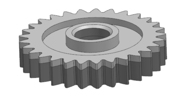
The plastic gear is shown in Figure 1. The selected material is polyoxymethylene (POM), which has good mechanical properties, and the molding shrinkage rate is 2%~3%. When the material temperature is high, it will change color. The cooling system should be designed. The circulation is uniform and good, and the temperature of the injection mold is guaranteed to be 80℃~100℃.
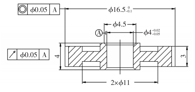
As shown in Figure 2, the maximum outer diameter of the plastic gear is the pulley, based on the middle ϕ 4mm shaft hole, the coaxiality requirement is ϕ 0.05mm, and the pulley and the middle hole ϕ 4mm and the full runout form tolerance requirement is 0.05mm . The selection of the main parting surface is based on the top surface ϕ 11mm maximum contour, the light-colored area is set in the fixed mold part, and the dark area and the intermediate shaft forming core are set in the movable mold part, which can ensure the accuracy of the plastic gear. The features with form and position tolerances and dimensional tolerances are determined according to the MT5 grade, and for free sizes, the tolerance value can be obtained according to the MT7 look-up table.
|

|
3 Design of gating system
(1) The diameter of the small end of the main runner is ϕ 0.5~ ϕ 1mm based on the nozzle diameter of the injection molding machine, the cone angle of the main runner is 2°~6°, the length is ≦60mm, and the diameter of the small end of the plastic gear main runner is ϕ 2.5 mm, the cone angle is 2°, and the actual length is 37mm.
(2) The runner adopts a commonly used U-shaped section, H=1.25R, R=0.5B, and the plastic gear runner H is 3.0mm, B is 3.9mm, and R is 1.7mm to make the plastic in a molten state. It quickly flows into the runners and is evenly filled, ensuring good pressure and uniform filling.
(3) The types of gates usually include side gates and point gates. Side gates can only be designed on the main parting surface. The design and processing are convenient, but there are gate marks. In order to obtain high-precision and high-finish plastic Therefore, the three-gate pouring method is selected. The advantage of the point gate is that there is no need to trim the burr, the gate will fall off automatically, and automated production can be realized. The plastic in the molten state flows radially from the gate to the surroundings, and 3 weld lines are formed at the flow junction. At the weld line position, the flow front tends to be parallel, and a low shrinkage area is formed along the weld line, which is not easy to deform, so as to obtain high Precision gears.
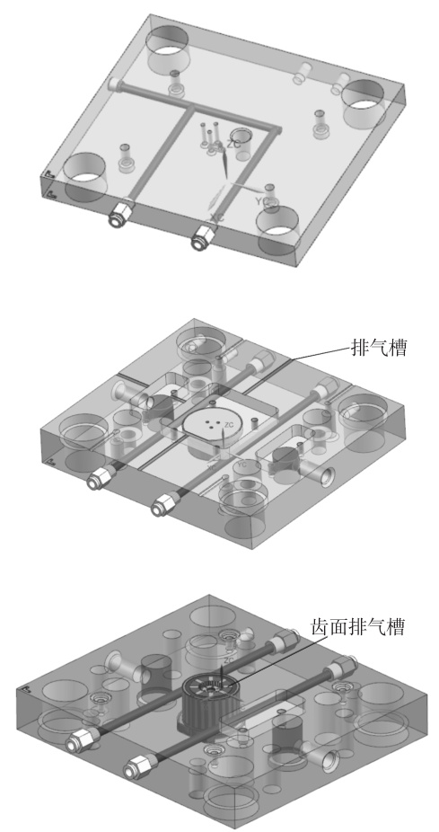
To sum up the analysis, combined with MoldFlow mold flow analysis software to determine the pouring point, the plastic gear pouring system design, as shown in the figure.
4 Cooling system design
When the mold is injected on the injection molding machine, the material of the plastic part is POM, which is a heat-sensitive material, and it is easy to change color when the temperature of the material is high. Therefore, in order to control the material temperature and molding time during injection molding, a cooling system should be reasonably set up to ensure that the mold temperature is maintained at 80°C to 100°C during injection. The stripper plate is equipped with a circulating water circuit, and the fixed and movable templates are each provided with 2 symmetrical and straight water channels. The cross-sectional diameter of the water channel is ϕ 8mm. The mold cooling system design is shown in Figure 4. The fixed template and the tooth surface are provided with exhaust grooves. In order to eliminate trapped air, the groove depth is less than the plastic overflow value, and the groove depth is 0.2mm.
 6 Launched the mechanism design
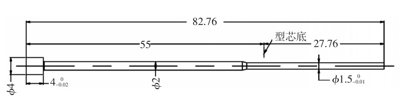
Commonly used push-out mechanisms include ejector rods, cylinders and pusher plates. The push plate is suitable for the shell and the plastic parts that are not allowed to leave marks on the outer surface. The cylinder is commonly used to push out cylindrical, ring-shaped and holed plastic parts. This kind of demolding force is uniform and the plastic part is small in deformation, but its accuracy is low. It can be used for gears below level 4. There is a gap in the middle of the cylinder, which increases Introduce the error. The ejector rod can eject the plastic parts uniformly. This kind of demolding can ensure the runout tolerance of the plastic parts, and the accuracy can reach 3 levels or more. According to the characteristics of the plastic part, the ejector pin is selected to push out, as shown in Figure 6.
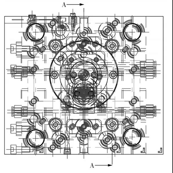
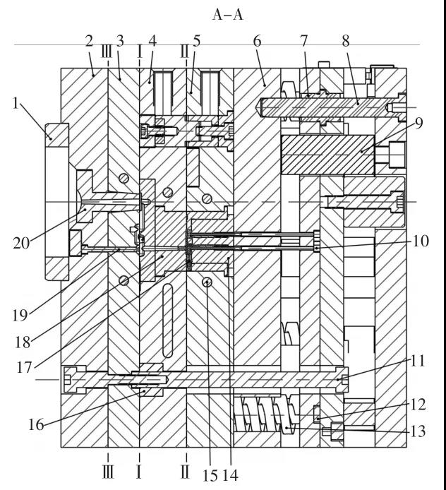
7 Mold assembly structure and its working process
The mold assembly structure is shown in the figure.
When the mold is opened, in order to prevent the gear plastic part from being strained or left on the side of the fixed mold, a spring 16 is designed on the small pull rod to make the Ⅰ-Ⅰ parting surface preferentially separate from the Ⅱ-Ⅱ parting surface. The gate is separated from the gear plastic part under the force of the rod 19; the movable mold moves to the top rod side of the injection molding machine. When the left side of the step of the small tie rod 11 touches the right side of the fixed template 4, the Ⅰ-Ⅰ parting surface moves End; the Ⅱ-Ⅱ parting surface is separated as the main parting surface. Due to the packing force of the gear plastic part, the plastic part remains on the movable mold core. The positioning pull plate on the upper side of the mold limits the distance of the Ⅱ-Ⅱ parting surface (The separation distance of Ⅰ-Ⅰ, Ⅱ-Ⅱ can allow the material head and the gear plastic parts to automatically blank); subsequently, the Ⅲ-Ⅲ parting surface is separated, and the gate material falls off; the movable mold continues to move to the right, and the ejector pin of the injection molding machine Pushing the bottom plate of the ejector rod to move, the ejector rod ejects the gear plastic part from the movable mold core, and the plastic part is automatically demolded.
When the mold is closed, the spring 13 on the reset rod 12 preferentially resets the ejector pin and drives the ejector pin 10 to return to the initial state. The mold side is closed, and finally the mold is closed.
8 concluding remarks
The mold adopts a three-plate mold point gate method for pouring, one mold and one cavity, and three parting surfaces are designed. The air is good, and the shrinkage and deformation of the gear plastic parts are solved. When designing the ejection mechanism, the Ⅰ-Ⅰ parting surface is given priority to the Ⅱ-Ⅱ parting surface. The pull rod and positioning plate are designed to limit the distance of mold opening. The ejector rod is used to push out to ensure the run-out tolerance of the plastic part. Accuracy. When the mold is actually produced, the mold mechanism is stable and reliable, and the quality and accuracy of the produced product meet the requirements of use.
6 Launched the mechanism design
Commonly used push-out mechanisms include ejector rods, cylinders and pusher plates. The push plate is suitable for the shell and the plastic parts that are not allowed to leave marks on the outer surface. The cylinder is commonly used to push out cylindrical, ring-shaped and holed plastic parts. This kind of demolding force is uniform and the plastic part is small in deformation, but its accuracy is low. It can be used for gears below level 4. There is a gap in the middle of the cylinder, which increases Introduce the error. The ejector rod can eject the plastic parts uniformly. This kind of demolding can ensure the runout tolerance of the plastic parts, and the accuracy can reach 3 levels or more. According to the characteristics of the plastic part, the ejector pin is selected to push out, as shown in Figure 6.
7 Mold assembly structure and its working process
The mold assembly structure is shown in the figure.
When the mold is opened, in order to prevent the gear plastic part from being strained or left on the side of the fixed mold, a spring 16 is designed on the small pull rod to make the Ⅰ-Ⅰ parting surface preferentially separate from the Ⅱ-Ⅱ parting surface. The gate is separated from the gear plastic part under the force of the rod 19; the movable mold moves to the top rod side of the injection molding machine. When the left side of the step of the small tie rod 11 touches the right side of the fixed template 4, the Ⅰ-Ⅰ parting surface moves End; the Ⅱ-Ⅱ parting surface is separated as the main parting surface. Due to the packing force of the gear plastic part, the plastic part remains on the movable mold core. The positioning pull plate on the upper side of the mold limits the distance of the Ⅱ-Ⅱ parting surface (The separation distance of Ⅰ-Ⅰ, Ⅱ-Ⅱ can allow the material head and the gear plastic parts to automatically blank); subsequently, the Ⅲ-Ⅲ parting surface is separated, and the gate material falls off; the movable mold continues to move to the right, and the ejector pin of the injection molding machine Pushing the bottom plate of the ejector rod to move, the ejector rod ejects the gear plastic part from the movable mold core, and the plastic part is automatically demolded.
When the mold is closed, the spring 13 on the reset rod 12 preferentially resets the ejector pin and drives the ejector pin 10 to return to the initial state. The mold side is closed, and finally the mold is closed.
8 concluding remarks
The mold adopts a three-plate mold point gate method for pouring, one mold and one cavity, and three parting surfaces are designed. The air is good, and the shrinkage and deformation of the gear plastic parts are solved. When designing the ejection mechanism, the Ⅰ-Ⅰ parting surface is given priority to the Ⅱ-Ⅱ parting surface. The pull rod and positioning plate are designed to limit the distance of mold opening. The ejector rod is used to push out to ensure the run-out tolerance of the plastic part. Accuracy. When the mold is actually produced, the mold mechanism is stable and reliable, and the quality and accuracy of the produced product meet the requirements of use.
 Building A, Dingfeng High-tech Park, Shapuwei Community, Song Gang Street, Shenzhen, China, 518105


 English