Design of Injection Mould for Face Shell of Intelligent Sweeping Robot
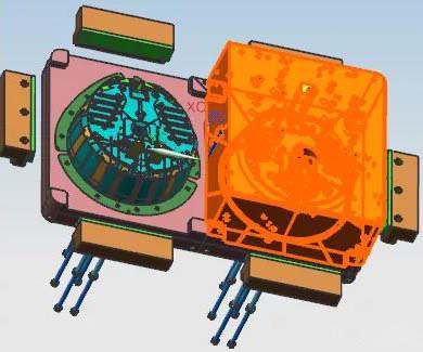
From the below picture, it is the product of the intelligent sweeping robot surface shell. The maximum size of this product is 384.90 mm x ø316.00mm x 130.80 mm, the average thickness is 2.00 mm, the material is PP, the shrinkage rate is 1.018, and it is 512.64 gram. The technical requirements for the plastic parts are that there must be no defects, such as flash, short shot, flow lines, gas mark, warpage deformation, silver streaks, unevenness etc.
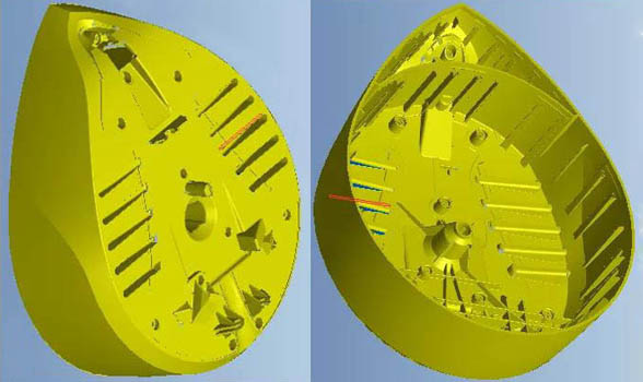
We can know from this picture that the structure of the plastic part is a closed shell, and the appearance looks like a peach. The top surface has ribs, pillars, convex shape and groove. The circle rib on the back of part makes a deep wall, and there are multiple deep strong ribs. There are also multiple ribs in the center of the inner top. Therefore, the difficulty of mold design lies in the ejection of the plastic part.
Please kindly check the mold design drawing as below picture. Due to this part is in large size, and with 2 cavities, so the mold needs to be in large size. The feed system of this mold use a hot runner system, and also as it is a large mold, using non-standard mold base with a size of 75108, the core and cavity are designed separately, which is convenient for two different machines to work at the same time.
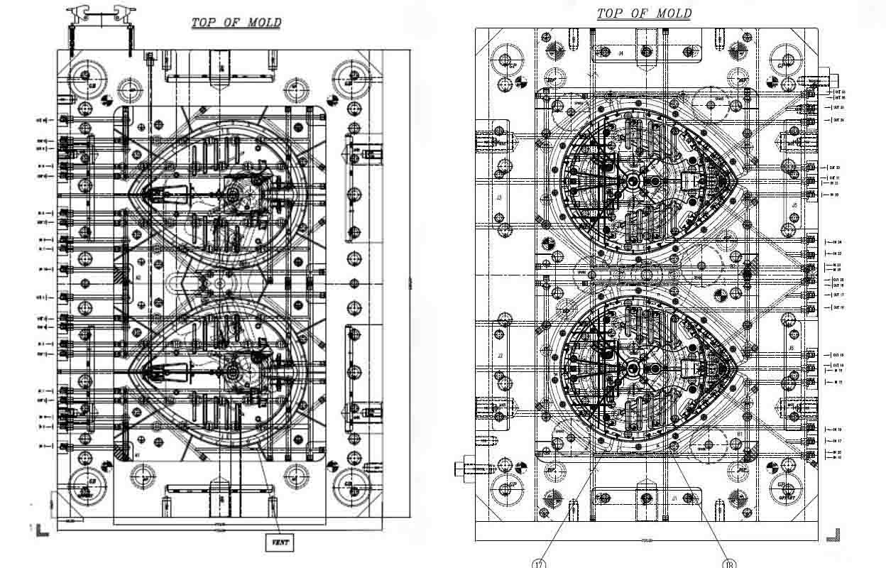
The cavity and core are positioned on four corners of the mold core to facilitate accurate mold clamping. Due to the cavity and core are big, the cavity and the precision frame are deep, the bottom frame and the frame of the mold core are difficult to match. Therefore, the inclination of 3゜ is designed on the two sides of the mold core away from the reference angle to cooperate with the precision frames of cavity and core. Cancel the slope at the matching position of the mold core and the precision frame. The purpose of this is to facilitate that the machining of the mold core is using the vertical edge as the machining reference, such as used for mold core during EDM. Six locking blocks 13 are designed on the edge of the mold base B plate, and the milling grooves are fixed on the B plate with screws. The locking block 13 is matched with the wear plate at an 8 ゜ inclined surface on the inclined surface of the A plate.
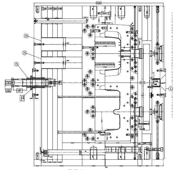
This is a large-size deep-cylinder plastic part, and the core has a deep rib, which makes it difficult to eject the part. Especially the semi-circular deep wall rib has greater tightening force on the core. The material is PP. This material has poor rigidity. When the packing force is large, it is easy to cause stress mark or offset, and it may also cause large deformation of the part. In summary, if the ejector pin is directly designed to eject by ejector, the part cannot be ejected effectively.
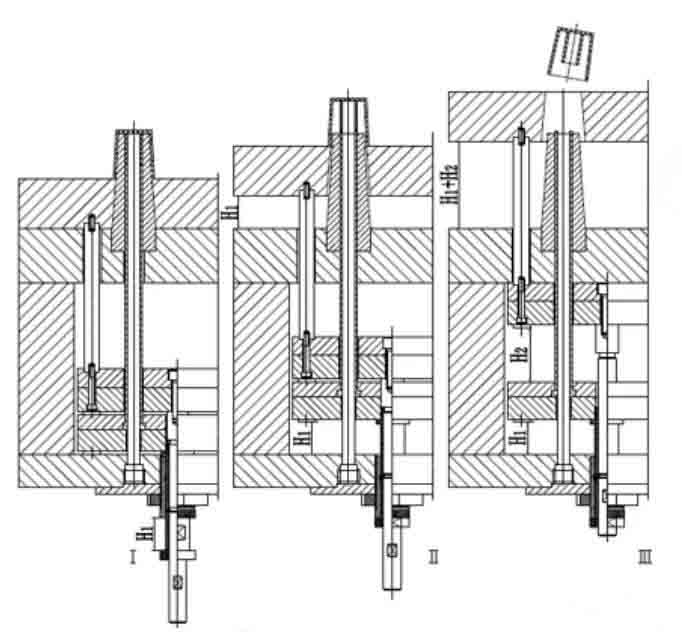
Normally, to eject the parts from the mold, whether it is a single or multi ejection, the ejection action is completed at one time. However, due to the special shape of the part or the demands of production automation, if the part is difficult to be removed from the mold or poor demolding is caused by a single ejection action, it is necessary to add another ejection action to successfully eject the part. For the parts with thin walls and deep cavities or complex shapes, sometimes in order to avoid excessive force on the parts once ejected, a second ejection is also used to disperse the ejection force and ensure the quality of the parts. According to the above analysis, this part must be ejected twice. The secondary ejection is usually that part or all of the demolding components are first released from the part together, and then some of the ejected components are stopped while the other part of the components continue to be ejected from the part.
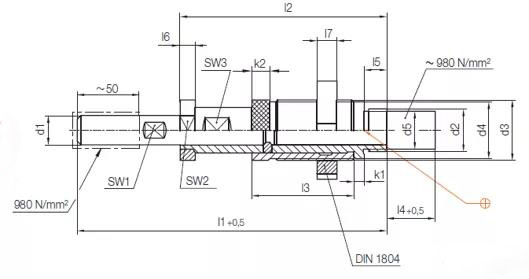
There are many mechanisms for
secondary ejection. The one commonly used in Europe is the HASCO standard secondary
ejection component Z169. Please kindly check its specifications as below
picture. The customer for this mold is from Italy, and Z169/40 is selected
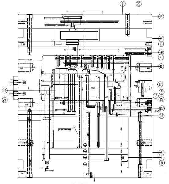
for the secondary ejection. The ejector plate is divided into
two parts, the upper side is designed with ejector pad and ejector pin, the
bottom of the ejector plate is designed with straight pins and ejector pins. Firstly,
the two layers of ejector plates act at the same time to demold the parts that
are difficult to demold, and then the center ejector pin ejects the upper
ejector plates to achieve demoulding of the plastic parts. The secondary
ejector device of HASCO adopts mechanical action to eject, which is reliable in
operation and long mold life. Regardless of the size of the mold,
a secondary ejection device is designed and designed in the center of the mold.
Previous :
Labor Day Holiday NoticeNext :
Why Is Aluminium Used In Die Casting Building A, Dingfeng High-tech Park, Shapuwei Community, Song Gang Street, Shenzhen, China, 518105
NO.1 Jinchang Road, Henan Industrial Zone, Chang’an Town, Dongguan City, China


For inquiries about our products or pricelist, please leave to us and we will be in touch within 24 hours.
© Copyright: 2026 Lyter Engineering Ltd. All Rights Reserved

IPv6 network supported
 English