Design of Injection Mold for the Base of Intelligent Sweeping Robot
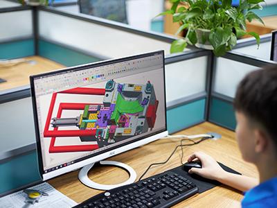
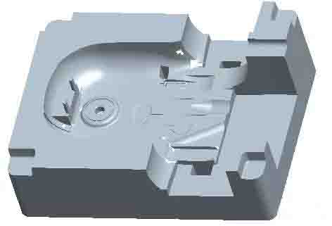
As the below picture shows, it is the product of the
intelligent sweeping robot base. The maximum size of this product is 403.13mm x 292.00mm x 170.30mm, the average thickness
is 2.30mm, the material is ABS, the shrinkage rate is 1.0045, and it is 777.51 gram. The technical
requirements for the plastic parts are that there must be no defects, such as
flash, short shot, flow lines, gas mark, warpage deformation, silver streaks,
unevenness etc.
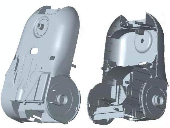
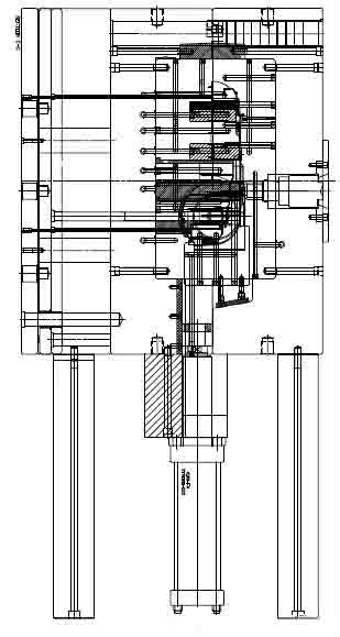
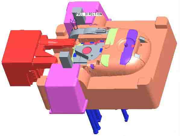
From below picture, we can know that the structure of the plastic part is complex. There is a hollow pillar on the top for the compressed air to pass through. The structure and shape of the rollers on the two sides of the part are complex, and the slider core needs to be designed. The tail structure of the part is also very complicated, requiring the design of a large slider and long-distance core pulling. The inner top surface of the part is designed with multiple deep ribs, the deepest part reaches 98.59mm, and there are also several convex pillars with deep height. The difficulty of mold design lies in the design of three sliders, the movable mold inserts, and the smooth ejection of the parts. The mold is designed as 1*1 cavity, the mold base is a non-standard mold base 7085, and the mold is large. In order to increase the mold clamping accuracy and resist the inward force of the cavity caused by the injection pressure, five inclined spacer blocks are designed on the four sides of the mold base. Tapered interlock is designed on the four corners of the mold coreThe tapered interlock angle is 5゜.
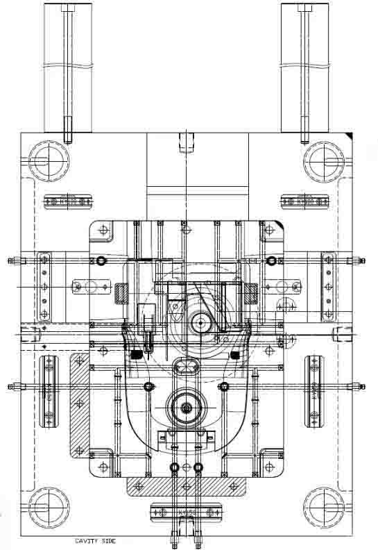
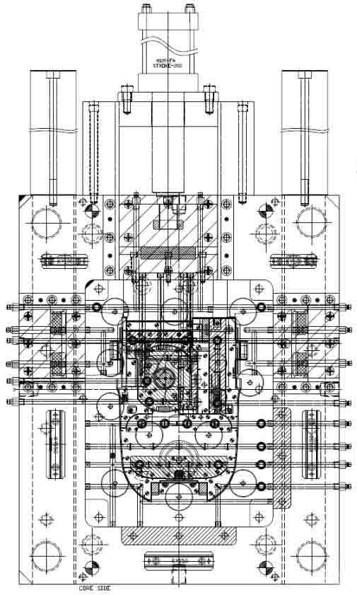
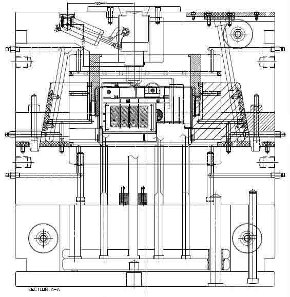
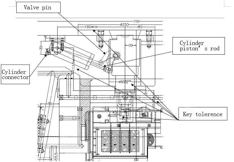
The gate of the mold is selected in the concave area on the top surface of the part, and use valve type hot nozzle. According to the different driving force of the valve gate, there are four valve driving ways-- spring type, cylinder type, hydraulic type and electronic type. The spring-driven spindle has a lower cost, but the system is difficult to control, the gate trace is unstable, so it doesn’t use a lot. The development of the valve hot nozzle is mainly reflected in the driving way. After decades of development, the current drive way of valve hot nozzle has been greatly developed compared with the past. At present, there are mainly hydraulic drive, pneumatic drive, electromagnetic drive and integral floating of the spindle fixing plate. Electromagnetic drive overcomes the shortcomings of possible leakage of hydraulic drive, and has been used in places where the environment is required such as dust-free workshops. pneumatic drive has developed into a way that one air cylinder drives 4 spindles. The design of the standard air cylinder makes the mold processing simple. The previous high-precision cylinder hole processing is eliminated from the template, and the processing of the cylinder is completed by the hot runner supplier. The overall floating of the spindle fixing plate can drive all the spindles, which is beneficial to reduce the number of cylinders and save mold space. This set of molds uses an oil cylinder drive valve hot runner system. We can know from below picture that the key assembly dimensions and tolerance design of the hydraulically driven spindles. Usually the cylinder is designed on the fixed mold base plate, it needs to take up bigger space. The processing accuracy of the cylinder is required to be high, which raises the cost of the mold. In the mold assembly process, in order to ensure the high-precision (coaxiality) coordination with the cavity plate, runner plate, and fixed mold seat plate, the processing accuracy of the corresponding matching parts of the mold must be improved. After the cylinder is processed on the fixed mold seat plate, a cooling circuit needs to be processed. When processing the gas path, be careful not to interfere with the cooling circuit. The biggest advantage of pneumatic drive is that there is no need to worry about air leakage and will not cause environmental pollution. Two core sliders are respectively designed at the roller installation positions on the two sides of the part. Both sliders are driven by angle guide pins. The structure and shape of the parts are complex, and the tightening force on the movable mold is large. Therefore, the straight ejector, the ejector pin and the ejector sleeve are designed.
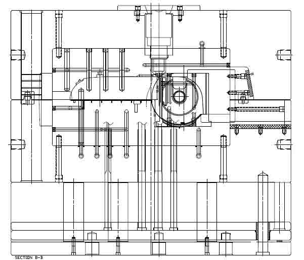
And as the part is large complicated. Cutting the insert at the deep
position is good for deep rib processing and polishing, and it is also good for air venting during
injection molding. All sliders,
cavities and cores are designed with cooling circuits to facilitate the normal
production of injection molding.
 Building A, Dingfeng High-tech Park, Shapuwei Community, Song Gang Street, Shenzhen, China, 518105
NO.1 Jinchang Road, Henan Industrial Zone, Chang’an Town, Dongguan City, China


For inquiries about our products or pricelist, please leave to us and we will be in touch within 24 hours.
© Copyright: 2026 Lyter Engineering Ltd. All Rights Reserved

IPv6 network supported
 English