Appliance Injection Mould Design for Plastic Washing Machine Cover Parts
Appliance Injection Mould Design for Washing Machine Cover
【Abstract】According to the structural characteristics of the plastic part, the parting method and optimal design of the plastic part are discussed. The reasonable design and layout can effectively avoid the interference between the multi-sloping roof structure, inserts and ejector pins. It also introduces the disassembly of inserts, ejector mechanism design, cooling water circuit layout and mold working process.
1 Structural analysis of plastic parts
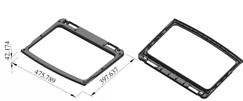
Figure 1 shows the upper cover plastic part of the washing machine. The size of the plastic part is 397.637×475.789×42.174mm. The material is ABS, and the shrinkage rate is 0.3%~0.7%. The core cavity of the dynamic and fixed model adopts the inlay type, and the material of the forming parts adopts 2738 steel. Plastic parts are appearance parts, and the outer surface needs to be frosted. There are many internal buckles in the plastic part. There are 31 inclined roofs in the whole mold, and the local bones are deep. Considering the exhaust problem, it is necessary to remove the inserts. In addition, the ejector rods, screws, and waterways make the inside of the mold intricate. , How to make a reasonable layout is a key issue to be considered in the design.
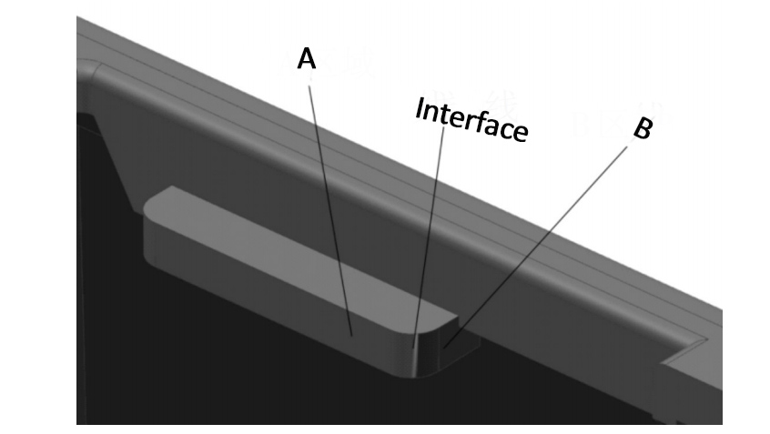
After completing patch materialization, drafting, and adjusting shrinkage in sequence, slope analysis is performed. According to the position shown in Figure 2, the surface of area A has a positive draft angle, and the surface of area B has a negative draft angle. There is a dividing line between the two, and there is a height difference between the B area and the bottom plane on the right. To better connect them together, you need to cut the B area surface for step processing.
In Figure 3, the buckle position needs to remove the inclined roof, but there is a bone position on the top. When the plastic part is pushed out, under the action of shrinking and tightening force, there may be shoveling of glue. Therefore, this place is in contact with the inclined roof. The surface needs to be treated with glue. In Figure 4, there are also high and low steps on the left side. Regardless of whether the parting surface is designed above or below, the cut surface needs to be processed for step differences. At the same time, better connection with the right side bone parting surface should be considered.
2 Parting design of plastic parts
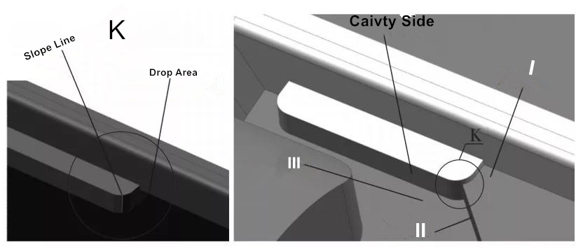
(1) Parting surface processing with a drop and segmentation difference at the corner.
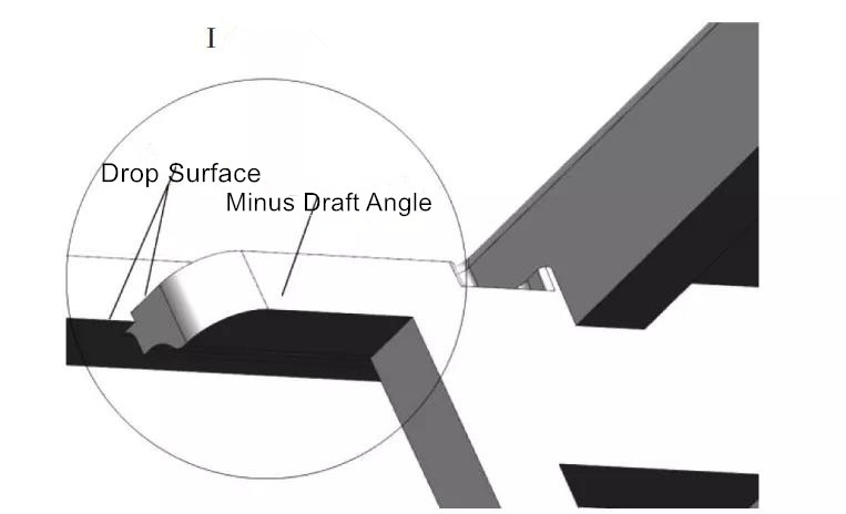
By observing the enlargement at K in Figure 5, we can see that if the "bottom step surface" on the right is enlarged to create the parting surface sheet body I, the side elevation of the right area will be cut as shown in the right figure; then extracted After the curve with equal slope in the +Z direction, it is stretched along the 45° direction to form the piercing surface of the sheet body II; and then the sheet body III is formed by expanding the surface. The sheet body I divides the original surface into two molding surfaces, a movable mold and a fixed mold, with opposite draft angles, forming a step difference.
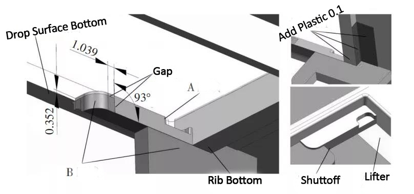
(2) If there is a drop, do a parting surface treatment where the rubbing surface forms a step difference at the plane.
As shown in Figure 6, the bottom surface of the right bone position is directly flat with the left side through the enlarged surface. The buckle here is the top of the inclined top. Appropriately add 0.1mm of glue to avoid the phenomenon of shoveling glue when ejecting. . The drop of the left step is 0.352mm, which extends directly from the bottom surface through the enlarged surface. The position of the step is designed on the right side of the arc angle, and it is inclined 3° to form a rubbing surface. When the vertical surface is cut, a zone A and zone B are formed. The zone A face is defined as the positive draft angle of the front mold face, and the B zone faces on both sides are defined as the negative draft angle of the back mold face. Then a step difference is formed between the two areas.
3 core cavity design
As shown in Figure 7, the size of the plastic part after adjusting the shrinkage rate is 399.625×478.168×42.385mm. Taking into account the large size of the plastic part itself, the inclined roof and the ejector pin occupy part of the position. The size of the glue surface, the layout of the cooling water circuit and the space for screw installation. Therefore, the length and width dimensions of the core cavity after parting are expanded by 50mm on the basis of the plastic part.
4 Inclined roof structure design
Observing the top structure design 8a, we can see that the buckle here is an inclined surface. If the inclined top is designed along the inclined surface, it will form a rubbing surface that is not easy to process and mold. Therefore, the step surface of the inclined top is wrapped up and made into a flat surface. Meet through the face. In Figure 8b, there is a groove on the right side of the bone. If the inclined top is wrapped in and pushed out, it cannot be displaced. If the side of the inclined top is directly attached to the side of the bone, the side of the inclined top will become a bevel. The upper end of the inclined top has a small size and a large bottom It cannot be ejected. For this reason, glue treatment should be carried out at this place to ensure that the two sides of the inclined roof are flat. At the same time, it is necessary to pay attention to the width of all inclined roofs to take integers. In Figure 8c, the inclined roof wraps around half of the surrounding bones. The purpose is that the bones are deeper, which is not convenient for processing and is not conducive to exhaust. The top surface of the inclined roof in Figure 8d has a stepped surface, it is easy to shovel glue when ejecting, and adding glue effectively avoids this problem. For all inclined roofs, the angle of the inclined roof is designed to be larger on the premise of ensuring sufficient ejection space, so that the ejection distance can be shortened.
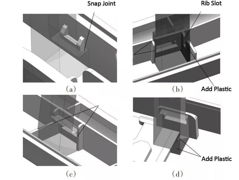
5 Insert split design
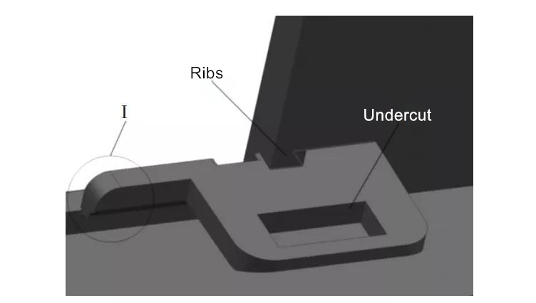
Analyze the structural characteristics of the plastic parts, and split the special inserts except for the inserts at positions such as insufficient strength and vulnerable parts. As shown in Figure 9a, the depth of the bone position at this position is 17.761mm, which is relatively deep, difficult to process, and the exhaust problem cannot be solved. The insert will encapsulate the bone position symmetrically, and the thickness of the insert is ensured based on the encapsulation position. Integer. In Figure 9b, this position is the edge of the bone position. The molten plastic is also easy to be trapped and filled or burnt during the filling process, so the insert is also covered with glue. In Fig. 9c, there are bone positions in 3 directions around the insert, all of which need to be encapsulated. In the design, it is only necessary to round the size of the insert as much as possible.
6 Design of ejector structure
Since there are 31 inclined tops in the mold ejection system, and there are many other related parts, a reasonable design sequence can reduce the trouble of subsequent adjustments. As shown in Figure 10, after the plastic part is divided, the sloping top is split first. After the mold base is called, the sliding seat must be designed in time, and the movement between the sloping tops must not conflict with each other; then the necessary The inserts are separated to solve the problems of trapped air and processing, and then observe whether there are more ejector pins to assist in ejection. Considering the large size of the mold, a standard distribution of 7 perforations is designed for balanced ejection, and then a symmetrical limit post is designed to control the ejection distance of 30mm. It should be noted that the limit post should be close to the perforation and lower the ejector panel and bottom plate. The layout of the support heads can be arranged from the center of symmetry to the two sides. The distance between the waterway and other parts is controlled to be more than 4mm and evenly distributed. Finally, the fastening screws of the cavity and core are placed in the remaining space. Just distribute it evenly.
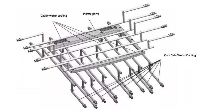
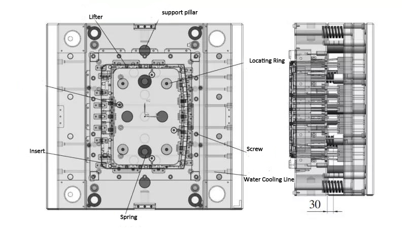
7 Cooling system design
Figure 11 shows the layout of the cooling water circuit. The movable mold part is affected by the relevant parts of the ejection system, and most of the waterways are designed in the X direction to be the most reasonable. Due to the large extruding block set in the mold, the water nozzles of the two water channels in the middle of the movable mold part are designed in the same direction. The fixed mold part is affected by the hot runner, extruded block, and fixed mold inserts due to the waterway, and the waterway cannot be reasonably arranged in the X direction. Therefore, the waterway can only be designed along the Y direction, which brings certain troubles to the installation of the mold. Can better play a cooling role.
8 Mold work process
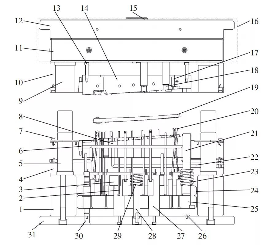
(1) The mold structure is shown in Figure 12. When the mold is opened, the mold starts to separate from the parting surface between the moving and fixed mold plates, and the plastic part 19 is glued to the surface of the movable mold core under the action of shrinking and packing force. The mold is opened along with the movable mold part.
(2) When the movable mold moves to a certain distance, the 7 ejector rods on the injection molding machine are pushed on the ejector pad 25, pushing the ejector pad 25 and the inclined top 20, ejector 2, and reset rod 21. When the components are pushed out, the springs 23 and 29 are also compressed by 30mm, and then the plastic part 19 falls off the movable mold.
(3) When re-closing the mold, the ejector system first resets under the action of spring force. When the movable and fixed formwork are attached, and the reset rod 21 is pushed against the fixed formwork, the ejector backing plate 25 is firmly attached to the trash nail. Ensure the accuracy of resetting the ejector system.
(4) Finally, the injection molding system will perform a new round of injection, pressure holding, cooling, and mold opening.
9 Concluding Remarks
Discusses several typical characteristics of plastic parts in terms of classification, and describes in detail the design method of step difference. There are a large number of inclined roof structures in the mold, and the relevant details of splitting the inclined roof and inserts are introduced, and the design sequence and details of the part layout of the movable mold are analyzed in detail. Part of the structure and characteristics of the mold have good reference significance.
Categories
latest blog
 Building A, Dingfeng High-tech Park, Shapuwei Community, Song Gang Street, Shenzhen, China, 518105
NO.1 Jinchang Road, Henan Industrial Zone, Chang’an Town, Dongguan City, China


For inquiries about our products or pricelist, please leave to us and we will be in touch within 24 hours.
© Copyright: 2026 Lyter Engineering Ltd. All Rights Reserved

IPv6 network supported
 English